
You are using an out of date browser. It may not display this or other websites correctly.
You should upgrade or use an alternative browser.
You should upgrade or use an alternative browser.
Coaxial SPDIF experiment
- Thread starter onlyoneme
- Start date


Mr Ee
Major Contributor
You need a new spyrograph? ")
tbh, I've no idea what you're trying to show us!
tbh, I've no idea what you're trying to show us!
I know, but I was getting much worse visualization when terminating with 75 ohm. Maybe the cable I've used is closer to 50 ohm. No idea what's the impedance usually for analog RCA cables.Spdif coax spec is 75 ohm if I remember it right. 1.2 m minumum length. Not sure how that might affect your results..
a 20mhz is not enough for this kind of observations
;-)
(
the rise times of the scope are too long for a relevant observation...
;-)..
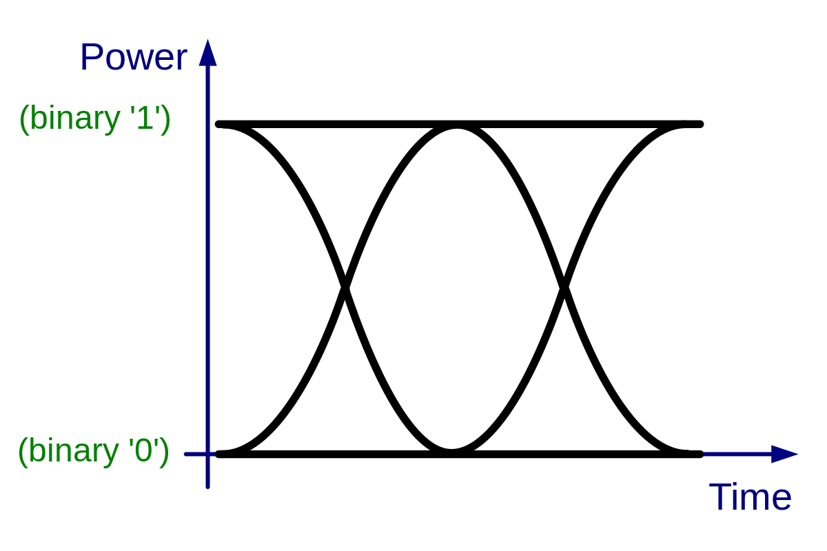
but an example of a really clean 44/16 signal at the output of a drive..
but again on a too limited scope like 50mhz .. the rise time marred by 7ns plus a little the probe ...to do well, you need 350-400mhz mini and adapted probe..i have but..not wiim pro i cant help...
;-)
(
the rise times of the scope are too long for a relevant observation...
;-)..
but an example of a really clean 44/16 signal at the output of a drive..
but again on a too limited scope like 50mhz .. the rise time marred by 7ns plus a little the probe ...to do well, you need 350-400mhz mini and adapted probe..i have but..not wiim pro i cant help...
Attachments
Last edited:
Mr Ee
Major Contributor
If I'm reading it right, you're showing that the digital signal degradation increases with the increase in frequency?
Isn't that to be expected?
Isn't that to be expected?
Why? SPDIF frequency for 192 kHz is less than 13 MHz.a 20mhz is not enough for this kind of observations
;-)
(
the rise times of the scope are too long for a relevant observation...
;-)..
but an example of a really clean 44/16 signal at the output of a drive..
but again on a too limited scope like 50mhz .. the rise time marred by 7ns plus a little the probe ...to do well, you need 350-400mhz mini and adapted probe..i have but..not wiim pro i cant help...
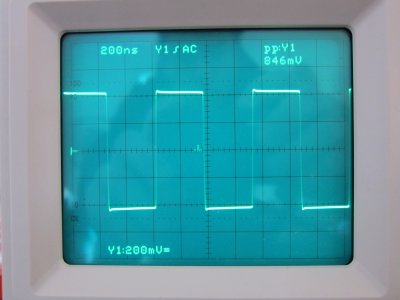
Different cable, still 50 ohm, different triggering.
48 kHz:

96 kHz:

192 kHz:

no, I have nothing on hand.(but these are square signals..explain the difficulty for a scope without a large margin in bw...)
automatic edge calculations give how many ns?...(x-17.5ns?)
(from memory the example I show was a + 3.5 4ns+7 type of flipflop output...)
but it's not a standard 0.5v spdif output?
automatic edge calculations give how many ns?...(x-17.5ns?)
(from memory the example I show was a + 3.5 4ns+7 type of flipflop output...)
but it's not a standard 0.5v spdif output?
Last edited:
I found a photo of the inside of the Pro here.ps
I would like to know if wiim has put a transformer in spdif output
but we still don't have a photo.
but if there is one side ac .. not a problem

Стример-плеер WiiM Pro/Wiim Mini/Wiim Pro Plus— а 12 000 рублей не могут спасти гиганта цифрового стриминга? Теперь с Roon.
Лев, фото внутри покажете?..
 www.dastereo.ru
cheer..I found a photo of the inside of the Pro here.
Стример-плеер WiiM Pro/Wiim Mini/Wiim Pro Plus— а 12 000 рублей не могут спасти гиганта цифрового стриминга? Теперь с Roon.
Лев, фото внутри покажете?..
the first images that I come across!
(my skills, and not helped by the cms, are limited but seem to me not to be isolated....)
;-)
Finally, thxI found a photo of the inside of the Pro here.
Стример-плеер WiiM Pro/Wiim Mini/Wiim Pro Plus— а 12 000 рублей не могут спасти гиганта цифрового стриминга? Теперь с Roon.
Лев, фото внутри покажете?..
It's a standard spdif output but impedance mismatch - 50 ohm termination plus a cable - probably affects a voltage.no, I have nothing on hand.(but these are square signals..explain the difficulty for a scope without a large margin in bw...)
automatic edge calculations give how many ns?...(x-17.5ns?)
(from memory the example I show was a + 3.5 4ns+7 type of flipflop output...)
but it's not a standard 0.5v spdif output?
I know I won't get a square wave representation, I don't expect this. But I think the noise and jitter can be still observed on the pattern.
hi frequencies loss and increasing impedance mismatches?Any thoughts?
Did you try other cables on 75 Ohm?
Similar threads
- Replies
- 391
- Views
- 41K